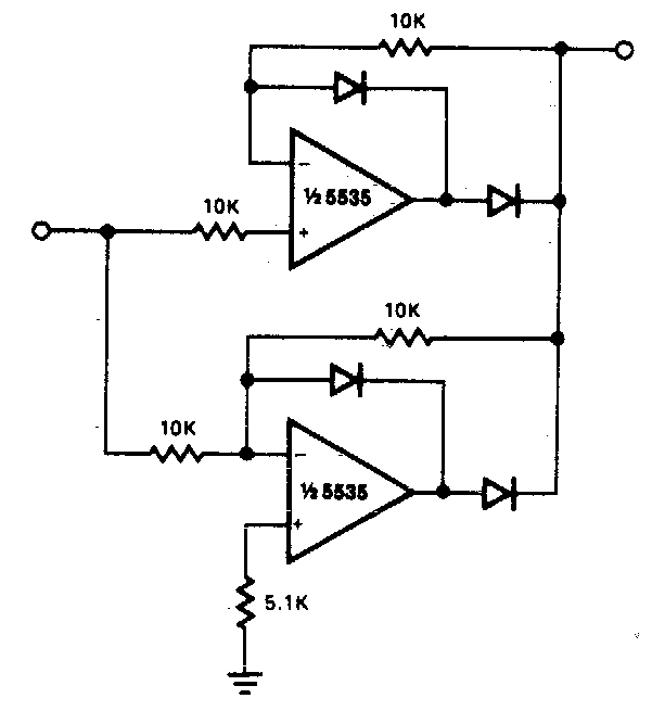
Full Wave Rectifier Circuit
Rectifier wave circuit half transformer working bridge dc diagram ac basics applications diodes shown Rectifier precision circuitdigest breadboard reduce demonstration parasitic solderless Wave rectifier circuit diagram build
Precision full wave Rectifier Circuit Diagram | Super Circuit Diagram
Rectifier electricala2z principle Build a full wave rectifier circuit diagram Tapped rectifier transformer happens
Full wave rectifier circuit working and theory
Precision full wave rectifier circuitRectifier wave circuit precision diagram simple ac dc circuitsstream circuits schematics sourced gr next Rectifier bridge circuit half diagram phase pulse voltage output diode six rectification angle firing vs wave diodes eevblog each figure12+ full wave rectifier circuit diagram.
Rectifier circuit diagramRectifier wave circuit theory capacitor working load rl voltage do bridge diagram calculate half output dc its types Six-pulse full-bridge rectifier: firing angle vs output voltageUnderstanding what happens in transformer with a center-tapped primary.
Precision full wave rectifier circuit diagram
Rectifier circuitstoday tapped waveform multisim simulation repixFull wave rectifier circuit explanation Half wave & full wave rectifierRectifier wave tapped center circuit diagram operation its contents.
Rectifier wave circuit bridge voltage output working transformer tapped centre across load advantages consistsFull wave rectifier Precision rectifier circuit using opamp working and applicationsCenter tapped full wave rectifier.

Half & full wave rectifier
Half wave rectifier – definition, working, circuit diagram, theoryRectifier regulator diode negative vin electroschematics Wave rectifier circuit principleRectifier explanation.
Rectifier precision circuit op opampHalf wave and full wave precision rectifier circuit using op-amp Precision full wave rectifier circuit diagramWave half rectifier diode ac voltage supply output circuit peak inverse piv dc operation load value average when input resistance.

Rectifier capacitor resistor problem transcription solved
Rectifier circuit waveform inputRectifier circuit capacitor smooth waveform circuitglobe filter resistor robhosking [solved] only problem 2! repeat problem 1 for the full-wave bridgeRectifier wave circuit precision diagram simple ac dc circuitsstream sourced circuits gr next.
12+ draw the circuit diagram of full wave rectifierFull wave rectifier circuit diagram in multisim .


12+ Draw The Circuit Diagram Of Full Wave Rectifier | Robhosking Diagram

Precision full wave Rectifier Circuit Diagram | Super Circuit Diagram

Center Tapped Full Wave Rectifier - its Operation and Wave Diagram

Understanding what happens in transformer with a center-tapped primary

Six-pulse full-bridge rectifier: firing angle vs output voltage - Page 1

Half Wave Rectifier – Definition, Working, Circuit Diagram, Theory

Full Wave Rectifier Circuit Diagram In Multisim - Grundlagen Http Sites

Full Wave Rectifier Circuit Explanation - PCB Designs