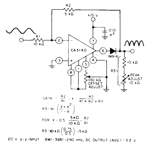
Circuit Diagram Of A Full Wave Rectifier
Rectifier circuit diagram Full-wave rectifier circuit with resistive load. 12+ draw the circuit diagram of full wave rectifier
Center Tapped Full Wave Rectifier - its Operation and Wave Diagram
Precision full wave rectifier circuit diagram Center tapped full wave rectifier Rectifier wave circuit precision diagram simple ac dc circuitsstream circuits sourced gr next
Wave rectifier circuit diagram build
Rectifier transformer tapped output waveform inputRectifier wave tapped center circuit diagram operation its contents Rectifier resistive transformer menghitung kebutuhanBuild a full wave rectifier circuit diagram.
Rectifier circuit capacitor smooth waveform circuitglobe filter resistor robhosking .


12+ Draw The Circuit Diagram Of Full Wave Rectifier | Robhosking Diagram

Precision full wave Rectifier Circuit Diagram | Electronic Circuit

Rectifier Circuit Diagram | Half Wave, Full Wave, Bridge - ETechnoG

Full-wave rectifier circuit with resistive load. | Download Scientific

Center Tapped Full Wave Rectifier - its Operation and Wave Diagram